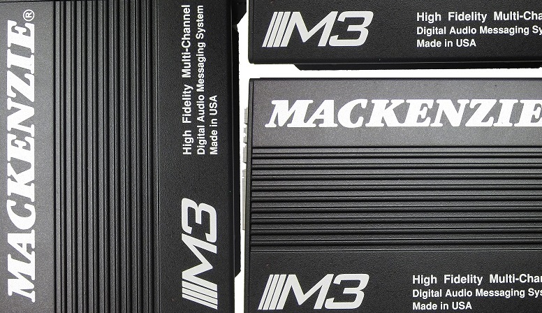
M3 · High-fidelity multi-channel digital audio player
The ultimate device with playback power and the flexibility to meet your audio design. Supports 1000's of messages and multiple audio channels.
The M3 system is the most flexible series of high fidelity, multi-channel solid state digital audio playback systems available to the industry. The system retrieves audio data from an SD Card memory and delivers superb full bandwidth sound quality.
Overview
Key features
- MPEG 1, Layer 3 (MP3) audio for scalable fidelity, from voice (7 kHz) to CD (20 kHz) quality
- Balanced audio output (up to 2 stereo channels)
- Internal 1 GB SD/SDHC memory card for up to 1000 minutes of 20 kHz mono audio (maximum 32 GB, about 22 days of audio)
- USB 2.0 key for easy audio file updates
- Up to 10,000 audio segments per channel
- Optically coupled 10/20 contact closures and RS-232 for control and status
- Standard, Retrigger, Play Once and Play While Active modes
- Playing relay contact (Form C)
- Composer software creates audio files from .WAV files
- Shock and vibration resistant
- Various configurations available
- Field upgradeable firmware
Applications
- Museums
- Amusement parks
- Theme events
- General public address installations
- Multiple language and sync track applications
Specifications
| Audio | |
|---|---|
| Output | Balanced stereo audio output |
| Storage | Internal SD card |
| Transfer | USB memory key; high-speed USB 2.0 host port |
| File formats | MP3 (32–320 kbps, VBR), WAV (44.1 kHz, 16 bit) |
| Bandwidth | 20 Hz–20 kHz; dynamic range 85 dB |
| Distortion (THD) | < 0.1% at 1 kHz |
| Level | +4 dB max., 150 Ω; stereo or dual mono; level potentiometers L/R per channel |
| Tone control | Bass and treble ±10 dB per channel (RS-232) |
| Control | |
| Manual controls | Contact closure and RS-232 |
| Start inputs | Optically coupled start 1–10 (1–20 on the M3.2) and stop per channel |
| Modes | Standard, play once per closure, play while active, re-trigger; plays 1–4 and delay 1–30 s by DIP switch |
| Relays | Playing relay per channel, Form C, 1 A at 24 VDC or 0.25 A at 110 VAC |
| Serial | RS-232, 115.2 kbaud default (9600 to 115,200), 8 N 1; ASCII commands |
| Models | |
| M3.1 | 1 balanced stereo channel, 10 message inputs, RS232 |
| M3.1+1 | 2 balanced stereo channels, 10 message inputs each, RS232 |
| M3.1+2 | 1 balanced stereo channel, 20 message inputs, RS232 |
| Messages and storage | |
| Messages | Up to 10,000 audio segments per channel |
| Capacity | 1 GB: about 1041 min at 20 kHz mono; SD/SDHC up to 32 GB |
| Loading | USB key, RS-232 (Y-Modem), or SD card from a computer; Composer software |
| Physical | |
| Dimensions | 5.7″ W × 6″ L × 2.4″ H |
| Mounting | Wall or table top; 1U rack package (M3-RM-x); painted aluminium extrusion chassis |
| Power | 12 VDC at 1 A, 2 pin Euro terminal |
| Operating temperature | −20 to +60 °C |
User manual in brief
Installation
The M3 high fidelity multi-channel digital audio player comes in three wall mount / table top configurations. The M3.1 has one balanced stereo audio channel with 10 message inputs; the M3.1+1 adds a second independent balanced stereo channel with its own 10 inputs; the M3.2 has one channel with 20 message inputs. All have RS-232. The M3-RM-x rack mount packaging is a 1U package with its own power supply that houses up to 4 M3 modules; it is ordered as a system and is not field upgradable. With no moving parts, the M3 suits automatic unattended operation, also in harsh environmental or mobile conditions.
- Find a space on the wall or table; for table top use, fit the included rubber feet. Leave about 6 inches in front of and behind the unit for access to the memory and wiring.
- Mount the unit with its wiring at least 18″ away from the power supply or other equipment that generates electrical noise.
- With the optional power supply (M3-PS, 12 VDC, 1 A), make sure a standard electrical outlet is available.
- Connect the audio outputs, then the control inputs and outputs.
- Set the DIP switches to the desired operation and verify that the memory card is installed.
- Connect and apply power, then test the unit’s operation.
Power and audio outputs
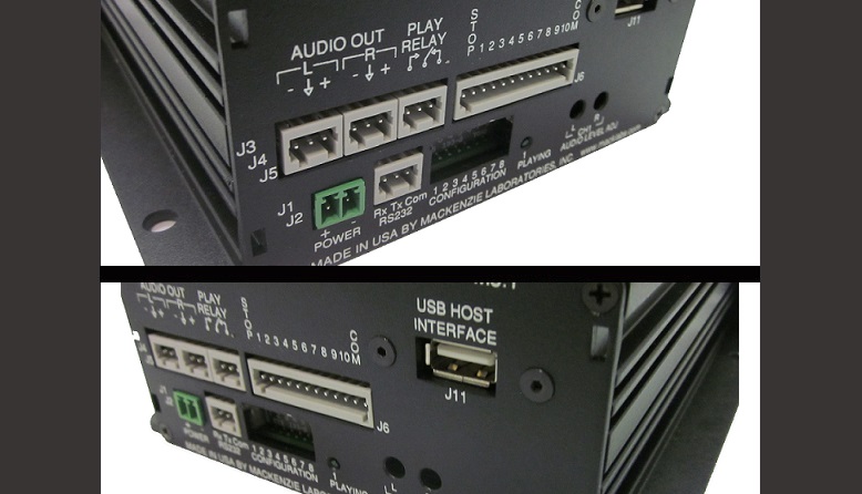
- Power entry: 2 terminal pluggable connector (3.81 mm Euro), + 12 VDC at 1 A, − ground; a rising clamp plug for wire up to 16 gauge.
- Channel 1 audio output: two 3 terminal pluggable connectors, L− (left, inverting), left ground, L+ (left, non-inverting), R− (right, inverting), right ground, R+ (right, non-inverting). Balanced, analog, stereo or dual mono, +4 dB maximum, 150 Ω.
- For an unbalanced (single ended) connection, use the non-inverting output and the output ground.
- Channel 1 audio level: two potentiometers set the left and right playback levels individually, continuous from −infinity to +3 dBm.
- M3.1+1 channel 2: a second set of two 3 terminal connectors with the same pin out, and two level potentiometers for left and right (−infinity to +4 dBm).
- Dual mono means separate material is stored on the left and right channels of a stereo pair, for zones or an audio sync track; the two sides of a pair cannot be triggered independently and run together from a single trigger.
- The spring clamp plugs accept wire up to 16 gauge; insert a jeweler’s screwdriver into the upper section to open the clamp, insert the bare wire, and remove the screwdriver.
Playing relay and LEDs
- Playing relay (one per channel): Form C contact (normally open, common, normally closed), active for the length of the playing message and released when it ends or is stopped; rated 1 A at 24 VDC or 0.25 A at 110 VAC, non-inductive load.
- Channel 1 playing LED (green): off when the M3 is not playing or has no power, on while channel 1 plays, blinking while the M3 executes other functions.
- Channel 2 playing LED (M3.1+1, green): off when not playing or without power, on while channel 2 plays, blinking during the boot procedure.
- If the USB key holds both a “Complete” and a “Delta” folder, the LEDs show an error indication.
Remote control inputs
Message playback is started and stopped by simple contact closures on a 12 position pluggable terminal strip; connecting any input to common (Com) activates its function. The control inputs are optically coupled.
- Stop: connect to common to stop message playback.
- Start 1 to Start 10: connect to common to play messages 1 to 10 on channel 1.
- M3.1+1: a second 12 position strip with Stop, Start 1 to Start 10 and Com controls channel 2.
- M3.2: a second strip above the first, with Stop, Start 11 to Start 20 and Com, plays messages 11 to 20 on channel 1; its Stop and Com are parallel to those of the base connector.
Configuration switches
An 8 position DIP switch sets the operation; a switch up is OFF, down is ON. The CPU reads it only at power up, so changes made while the unit is powered have no effect until the next power up.
- Switches 1 and 2, number of plays (global, for repeating messages because of noise or for clarity): OFF OFF once, OFF ON twice, ON OFF three times, ON ON four times.
- Switches 3 and 4, delay between plays (global): OFF OFF 1 second, OFF ON 5 seconds, ON OFF 10 seconds, ON ON 30 seconds.
- Switches 5 and 6, play mode: OFF OFF standard operation, OFF ON play one sequence per closure, ON OFF play while active, ON ON re-trigger.
- Switch 7, play next: ON lets Start 10 play the next valid message sequence (the first input after power on plays message 1); all modes are supported and the other start inputs are disabled. OFF disables it.
- Switch 8, memory protect: ON locks the message memory so messages cannot be overwritten by accident; OFF unlocks it.
Play modes
A message sequence is the message played the selected number of times, separated by the selected delay.
- Standard operation: a momentary closure plays one sequence of that input’s message. A maintained closure repeats the message until the input is released, then the current sequence finishes. With several inputs held, the unit plays the first message and then cycles through the other active ones in the order received; the lower input number wins when inputs arrive at exactly the same time. A momentary closure released before the playing message ends is ignored; messages are queued only when inputs arrive simultaneously.
- Play one sequence per closure: a maintained input plays the sequence once; the input must go inactive for a preset time before it is recognized again, while other inputs are served normally. Momentary activations are queued and played in the order received, up to 16 messages including the one playing; further activations are ignored. A stop ends the current message and the next in the queue starts.
- Play while active: the message plays as long as the control signal is held and aborts immediately when it is removed. If the input is still active after the delay that follows the sequence, another sequence starts. With several inputs held, only the lowest numbered message plays and repeats.
- Re-trigger: a new activation, of another message or the same one, stops the playing message and plays the new one. A maintained activation plays the sequence once; simultaneous inputs play only the lowest numbered message.
Audio files and memory
Messages are stored on a FAT formatted, non-volatile SD card (1 GB included), so no battery backup is needed; they are randomly and instantly accessible, and each may have a different length, also when replaced. Composer software (M3-SW) lets a Windows computer build programs from .WAV files and convert them to MP3. Files can be copied to the SD card from a computer, or loaded into the M3 over the USB port or the RS-232 port. Card replacement is not needed in normal use; contact the factory for instructions if it is.
- Formats: WAV (44.1 kHz, 16 bit) or MP3 (44.1 kHz, 32–320 kbps, VBR); mono or stereo. A mono message plays the same on both left and right channels. Message lengths may be from a couple of seconds to several hours.
- Naming: 1.mp3 or 1.wav goes to message position 1 and is played by Start input 1; 2.mp3 or 2.wav to position 2, and so on.
- If the card has two files with the same name but different extensions, the MP3 file plays and the WAV file is ignored. A file with a doubled extension (3.mp3.mp3) is neither recognized nor played.
- USB type “A” connector for a USB memory key: a “Complete” folder deletes all files on the M3 and replaces them with the folder’s audio files; a “Delta” folder replaces files of the same name.
- MP3 data rates (mono): 7 kHz bandwidth at 32 kbps, 4 minutes per MB; 15 kHz at 64 kbps, 2 minutes per MB; 20 kHz at 128 kbps, 1 minute per MB.
- SD card capacities, mono at 7 / 15 / 20 kHz: SD-1GB about 4164 / 2082 / 1041 minutes; SD-2GB 8328 / 4164 / 2082; SD-4GB 16656 / 8328 / 4164. Stereo or dual mono stores half as much.
RS-232 control
The RS-232 port (Rx, Tx, COM ground) gives extended control from a programmable logic controller (PLC) or manually from a terminal program such as HyperTerminal; the protocol is human readable ASCII, with the prompt M3>. It provides playback control, diagnostics, settings and message downloads. Defaults are 115,200 baud, 8 data bits, no parity, 1 stop bit, no flow control; there is no error detection, so the link is meant to be short and reliable. Each command ends with
- PLY: play snippet (1 to 9,999) on channel (1, 2, or 3 for both),
times (1–99), with a pause of 0 to ±99 (seconds, or minutes when negative); example PLY20,1,2,10. PLYI interrupts the playing message, plays the snippet at once, then replays the interrupted message. - STP: stop the message playing on a channel (1, 2, 3 for both, none for both); the next queued message then plays. STPALL stops both channels and purges the queue.
- RST: system reset (warm boot); ULD and DLD: read a file from, or write a file to, the memory card by Y-Modem; DEL: delete a file from the card.
- SPD: RS-232 speed, 0 = 9600, 1 = 19,200, 2 = 38,400, 3 = 57,600, 4 = 115,200 baud (default); the new rate must be confirmed with Y, or the unit returns to the old rate after 20 seconds.
- CFG: restore default configuration; FMT: format the SD card, erasing all files; SHP: format the card and restore factory defaults (each asks for confirmation).
- DLY: delay before play, 0–99 seconds; PAS: pause between plays, 0 to ±99 (seconds, or minutes when negative); PLS: number of plays per trigger, 1–99. These three apply to contact closure triggers only, not to RS-232 triggers.
- PRI: message priority, 1 enables and 0 disables a snippet; kept through power cycles.
- SYS: system information (model, firmware version, date and time, SD card size, number of audio files, plays, delay, pause, bass and treble); LST: list all commands; DIR: message listing, with “x” for missing and “d” for disabled messages.
- TIM and DTE: set the time of day and the date; BAS and TRE: bass and treble per channel, ±10 dB.
- FIRMWARE: field firmware update; the unit answers “Start 1K-XModem Download” and accepts the M3APP.bin file by 1K X-Modem within about 60 seconds, or resets.
Documents
| Document | Content | Format |
|---|---|---|
| Spec sheet | Specifications | |
| Operation guide | User manual, version 1.3 |
Images