OPM-3SM · Multiple-channel page stacker, feedback eliminator and messaging system
a comprehensive system that combines page stacking, feedback elimination, pre-recorded messaging and background music control into a single device.
For high traffic environments, Mackenzie produced this unit with three page port inputs that can record simultaneously, and then be streamed sequentially through your paging system The OPM 3S offers a priority input that overrides the stacking and messaging functions to provide immediate, real time access to the paging system. This unit also offers up to 99 messages or 8 minutes of audio.
Overview
Key features
- 3 channel page stacker and feedback eliminator
- Priority input
- Station or Dry Loop / Loop Start operation
- DTMF support for zoning
- 99 pre-recorded messages in non-volatile FLASH memory
- Message triggering via start input or host telephone system workstation
- Industrial construction
- Background music support
- Rack mount chassis
- Power pack included
- 1 year warranty standard
Specifications
| Audio | |
|---|---|
| Output | Adjustable dual output, 8 Ω / 600 Ω |
| Background music | Background music control |
| Bandwidth | 100 Hz – 8 kHz |
| Audio inputs | 3 page, 1 priority and 1 messaging input, RJ12; each Analog Station, Dry Loop or Loop Start; BGM line input on RCA, 0 dBV, with level control |
| Messages and storage | |
| Storage | 8 minutes (99 messages) |
| Page inputs | 3, recording simultaneously, played back in sequence |
| Priority | Priority input overrides stacking and messaging for live paging |
| Security | Pre-recorded messaging subsystem |
| Page stacking | Up to 16 pages or 4 minutes per channel; playback queue of 32 pages, first in, first out |
| Control | |
| Delay between messages | 1, 3, 5 or 10 seconds |
| Message repeats | Once or twice |
| DTMF control | From the messaging input |
| Start contacts | 10, for triggering messages from external devices |
| Relays | Busy, playing and recording solid state relay contacts, 24 VDC at 100 mA max |
| Indicators | System OK, recording, playing, busy; off hook and level or activity per input; record and play per channel |
| Physical | |
| Mounting | 1U 19″ rack chassis, 18 gauge cold rolled steel |
| Power | 12 VDC, 1 A power pack, UL and CSA |
| Weight | 7 lb |
| Warranty | 1 year standard |
User manual in brief
Installation
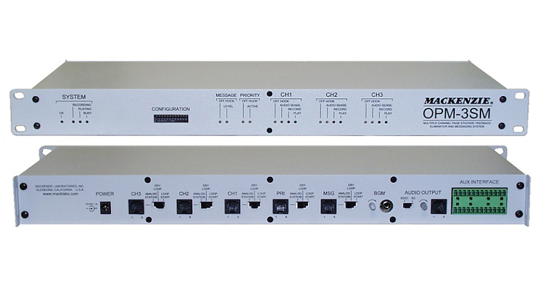
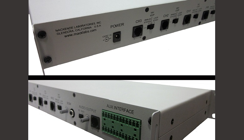
The OPM-3SM is a standard 1U 19″ rack mount chassis. The front panel carries the status LEDs and the configuration switches; the back panel carries every electrical connection, a port configuration switch next to each audio input, the BGM and output volume controls, and flanges on each side for strain relief of the wiring.
- Mount the unit in a rack or on a table with the supplied screws, with its wiring at least 18″ away from the power supply and from other equipment that generates electrical noise.
- Plug the supplied 12 VDC, 1 A power pack (UL and CSA) into a standard outlet that is not controlled by a wall switch.
- Connect the PBX or audio sources and the paging system, set the DIP switches, then connect power; the System OK LED lights green. Test the unit.
Connections
- Power: 12 VDC at 1 A through the barrel connector; use only the factory supplied power pack. The chassis is connected to the negative side of the supply.
- PAGE CHANNEL 1, 2 and 3 (RJ12, 6 position): pin 1 abort, stops and deletes the recording when connected to ground (pin 5); pin 2 record input, records for the duration of a closure to ground; pin 3 audio ring/return; pin 4 audio tip/signal; pin 5 system ground; pin 6 not used.
- PRIORITY (RJ12, 6 position): pin 2 priority input, active for the duration of a closure to ground (pin 5); pin 3 audio ring/return; pin 4 audio tip/signal; pin 5 ground; pins 1 and 6 not used.
- MESSAGING (RJ12, 6 position): pin 3 audio ring/return; pin 4 audio tip/signal; the other pins not used. Operation of the pre-recorded messaging system is through this port.
- BGM INPUT (RCA jack): background music at 0 dBV nominal or less; tip is signal, sleeve is return.
- AUDIO OUT (RJ12, 6 position): pin 2 playing relay, normally open; pin 3 audio return; pin 4 audio signal; pin 5 playing relay, common; pins 1 and 6 not used. These relay contacts are paralleled with positions 9 and 10 of the paging control interface.
- AUX INTERFACE, top row, messaging playback (12 position Euro-style pluggable): 1 ground (common); 2 to 11 play messages 1 to 10; 12 not used. A momentary closure (100 ms) between a play input and ground plays that message once; several closures queue the messages in the order received.
- AUX INTERFACE, bottom row, paging control and status: 1 ground (common); 3 priority page; 4 stop the playing message; 5 play the next page in the queue; 7–8 BUSY relay (common, normally open); 9–10 PLAYING relay (common, normally open); 11–12 RECORDING relay (common, normally open); 2 and 6 not used. Status outputs are solid state relay contacts rated 24 VDC at 100 mA maximum.
Port configuration and controls
- Port configuration switch, one 3 position slide switch for each of the five inputs (channels 1–3, priority, messaging): ANALOG STATION (left), 900 Ω, ring trip voltage 75–105 V at 20–60 Hz; DRY LOOP (center), 600 Ω line level (−10 dB nominal); LOOP START (right), 900 Ω with 24 VDC talk battery, for loop start trunk ports.
- Audio output mode switch: right for line level (+4 dB/600 Ω), the default; left for power level (500 mW/8 Ω), for longer runs or when the line level output is not enough.
- Output volume: level delivered to the paging system, shipped set to 1:1 gain; clockwise raises it.
- BGM level: sets the level of the background music sent to the output; clockwise raises it.
Indicators
- System OK (green): unit on; flashing indicates an error condition, contact the factory.
- System Recording (red): a recording session is active on any paging input. System Playing (green): the output is active with a page or the priority input. System Busy (yellow): any paging input is recording, playing or in a delay, or a priority announcement is being made.
- Message input: Off Hook (yellow, the messaging system is accessed over a phone circuit, loop current flowing) and Level (yellow, audio present).
- Priority input: Off Hook (yellow, loop current flowing) and Active (yellow).
- Page channels 1, 2 and 3: Off Hook (yellow), Audio Sense (yellow, audio present on that port), Record (red) and Play (green).
Configuration switches
A 12 position DIP switch on the front panel, up is OFF and down is ON. The settings are read at power up, so power must be cycled for a change to take effect. A maintained closure on a channel’s record input always records on that channel, whatever the settings.
- 1–2, record activation: loop current detect (1 OFF, 2 OFF, default), the OPM-3SM sources 24 VDC talk battery and records while loop current flows, for Analog Station and Loop Start ports; audio sense (1 OFF, 2 ON), records from detected audio until 3 seconds of silence, for all port modes; DTMF (1 ON, 2 OFF), records from a valid DTMF tone until 3 seconds of silence, for Analog Station and Loop Start ports; the activating tone is stripped from playback.
- 3, DTMF tone stripping: active (default) or not active; zone control tones at the start of a page are stripped from its repeat.
- 4, stripping method: only the tones at the start of a page (default), or tones anywhere in the page, restarting the recording.
- 5–6, DTMF allotment: unlimited (default), 4, 3 or 2 tones; a page with more tones is aborted.
- 7, “##” abort: enabled (default) or disabled; # pressed twice within one second aborts the recording with a busy back tone.
- 8, play mode: automatic (default) or manual; in manual mode a momentary closure (100 ms) between pins 1 and 5 of the paging control interface plays the pages.
- 9, pre-page tone: disabled (default) or enabled, before each page in the queue but not before repeats.
- 10, number of plays: once (default) or twice.
- 11–12, delay between plays: 1 second (default), 3, 5 or 10 seconds, between pages and between repeats.
Page stacking and priority
Each of the three page channels eliminates feedback by recording the incoming page and playing it back after the caller hangs up, can repeat each page for intelligibility in noisy areas, and stacks up to 16 pages or 4 minutes of audio. The channels can record at the same time and while the system is playing. DTMF tones can be recorded and regenerated, or blocked, for zone controller applications.
- Playback queue: up to 32 pages from the three page channels and the messaging input, first in, first out. Pages play in the order their recordings complete, whatever the input: a short page finished on channel 2 plays before a long one still recording on channel 1.
- Priority: Analog Station, Dry Loop or Loop Start connection gives immediate, live access to the paging system, whatever the record activation switches. Priority pauses the queue; when the priority page ends, playback resumes from the beginning of the interrupted message.
- Automatic mode, the factory default, is the most widely used for paging and needs minimal installation.
Pre-recorded messages
Up to 99 messages in 8 minutes of FLASH memory, recorded and stored permanently for standard or frequently used announcements such as security messages. They are recorded and played from an extension of the host telephone system connected to the messaging input (Analog Station, Dry Loop or Loop Start), or played from the ten start contacts of the auxiliary interface, for sensors and alarms. The Message Off Hook LED shows a connection in Loop Start or Analog Station mode. A steady tone confirms an accepted command; a fast busy signal means an incorrect one.
- # (End): stop recording or exit a command.
- *0 (Stop): stop playing all triggered messages.
- *3xx (Delete): delete the message at location xx.
- *5xx or xx (Play): play the message at location xx to the audio output.
- *6xx (Review): listen to a message through the handset only, not on the audio output.
- *7xx (Record): record into location xx; only empty locations can be recorded, so delete a message before updating it.
Background music and output
The background music source is mixed with pages and pre-recorded messages and plays over the paging system whenever the system is idle; it is muted while a page or message plays. All audio from the page channels, the priority input, the messaging system and the BGM input goes to the single audio output, the interface to the zone controller, amplifier or public address system.
Limits and troubleshooting
- Page aborted with a busy back tone → it was longer than 1 minute, the maximum per page, or it reached the end of memory.
- Busy back tone at the start of a page → that channel’s memory is full; wait for queued pages to play.
- Page not played → it was shorter than 1 second, or held 3 seconds or more of silence (deleted, with a busy back tone).
- Fast busy signal after a DTMF command → the command was not accepted; to record over a message, delete it first with *3xx.
- System OK LED flashing → error condition; contact the factory.
- Changed configuration switches have no effect → cycle power.
Documents
| Document | Content | Format |
|---|---|---|
| Spec sheet | Specifications | |
| Operation guide | User manual, version 1.4 | |
| Quikey: connectivity detail | Connectivity detail |
Images
Related models: Page management
| OPM-1S | Page stacker and feedback eliminator | |
|---|---|---|
| OPM-3SM | Multiple-channel page stacker, feedback eliminator and messaging system | This page |